While hooking up my Sure LED Matrix up to my Raspberry Pi using USB worked… it could work better. Using the Driver board from Sure, you can only scroll character by character which doesn’t look that smooth. So instead of using the driver board to interface with the matrixes, I directly connected it to the Raspberry PI so I can control things at the pixel level.
The Sure Electronics LED boards use the HT1632C driver chip. You communicate with the chip using SPI. The RPi natively supports SPI right out of its GPIO port. SPI simply defines the low level electronic communication, in order to talk to the HT1632, you need to use specifically crafted messages, and this takes some programming.
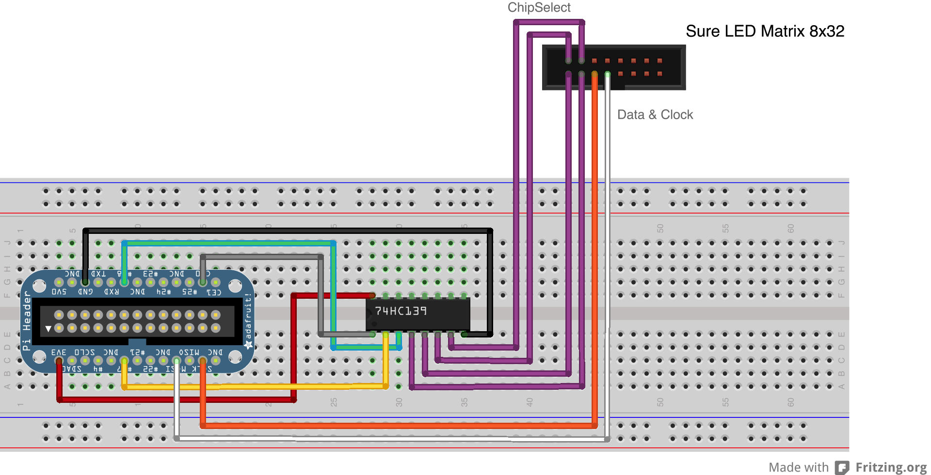
Before we get to that, lets talk about how to wire the LED Matrices together and connect them to the RPi. The Matrices are connected together with 16 wire ribbon cable. All of the boards are connected together serially and then the first board is connected to a bread board you have connected to your RPi. Each LED Matrix has a dip switch on the back that lets you set its ID, (1-4). In the Ribbon cable there are 6 important wires for communicating. There are 4 chip select wires, a clock wire and a data wire. Each of the chip select wires corresponds to one of the Matrix IDs. When you set a chip select wire high, you are communicating to that board. The Data and Clock wires are used to do the communicating.
The only problem is that the RPi only has 2 SPI chip select lines and you have 4 Matrices you need to communicate with. Ugh! I had no idea what to do, so I posted the question on the RPi forum and got a couple of good solutions. It turns out the way you get around this is by using a multiplexer that is controlled separately by some of the other GPIO pins. The simplest approach is to use the 74HC139. It uses 2 lines to select between 4 different output lines, with only 1 being high at a time. The chip actually contains 2 multiplexers, so with one chip and 4 lines, you can have 8 output lines. If you are going to be outputting to more lines, it looks like the 74HC595 is the way to go. It is a little more complex to interface with, but if you chain them together, you can have tons of output lines. Here is how I wired everything up:
I got a couple of parts from AdaFruit to make it easier to put everything together:
- Pi T-Cobbler Breakout Kits – $7.95
- Pi Dish – $22.50
- Breadboarding wire bundle – $6.00
- Female DC Power adapter – 2.1mm jack to screw terminal block – $2.00
With all of this, it was really easy to wire things together. The Pi Cobbler took a little soldering, which was fun. I order the IC and the parts to make a ribbon cable from Mouser:
- 74HC139 – $0.41
- 16 Conductor Ribbon Cable – $0.64 a foot
- Ribbon Cable Header – $1.63
- Breadboard Compatible Header – $2.79
There is one thing I am still not sure of… how long can the ribbon cable can be. I originally went with a 12′ cable. It was being a little glitchy though, so I now have it down to 6′ and it seems to be working good. You will also need a good 5v power supply to power the LED Matrices. If all four are going, it could pull about 1200MA. I borrowed one from a USB hub. The Female DC Socket from Adafruit, makes it easy to attach a salvaged power supply. Once you have this wired up, it is time to start programming. To keep things simple you could just start with 2 displays and use the 2 chip select lines built into the RPi. The programming is pretty simple. The WiringPi project helps get you start using GPIO lines and SPI.
Once you have everything wired up, it is time to start programming. In order to make the LED Matrices do aynthing you need to send message over SPI. The messages are a series of different patterns of bits. To send a Command to a matrix, you start a message out with the bits: 1-0-0 followed by a number that represents command you want to send (in binary) followed by the setting for that command. To Write data to a matrix, you start a message with the bits: 101 followed by the matrix’s memory address you would like to and then the pixel data you would like to write.
The matrix’s addresses start in the upper left hand corner at 0. Each memory address covers 4 pixels. The 0 address covers the top 4 pixels in the first column. Address 1 covers the bottom 4 pixels of the first column. Address 2 covers the top 4 pixels of the second column from the left, and so on.
Of course having to specify all these addresses would slow things down if you are trying to fill an entire screen. Instead, you can also specify an address you wish to start writing from and then continue to write pixel data to fill in sequential sets of pixels after the one you have addressed. So if you want to write the data for an entire matrix, you start at address 0 and write out all the data.
There are of course a few wrinkles. The first is Endian stuff. Endian determines the order in which the bytes in multibyte variables get stored. When you are constructing Messages in memory using memcopy and then passing the address to the SPI function, Endianess doesn’t seem to be a problem. However when you are construct individual message inside a Word, (which is 2 bytes) and then passing a pointer to the variable’s memory, Endianess becomes a problem. In order to make this work right you have to first write to the variable and then swap the order of the 2 Bytes which make up the Word. Confusing. Long story short, if things are not working, it could be this endian stuff.
The other thing that comes up is that some of the message don’t easily fall across 8-bit boundaries. This generally isn’t a problem and you just end up sending some extra 0s padded on the end of your message. However, when you are trying to write the long blocks of pixel data to a matrix, this is a problem. To construct this message, you have to first write to the message the bits: 1-0-1, followed by the bits: 0-0-0-0-0-0-0 to signal that you want to write to the first address. Now you can just copy your pixel data from where it is cached in memory to the spot in memory where you are constructing this message. The problem is that with the standard functions in C, you can only specify memory copies based upon 8-bits, and with this message you are starting 10-bits in. The solution is to find a way to do bit-level offsets when copying. Doing this is a pain and tricky to do efficiently. Luckily I found a bit of code that explains this.
I have all the code for this up online here: https://github.com/robotastic/SPI-LED-Print It is not pretty, but it should give you a general idea for how to write to an LED Matrix using SPI and using the GPIO pins to multiplex the output. I used this code as the basis for building a C++ NodeJs module that does this. I will post more on that next.
Comments
10 responses to “Raspberry Pi to LED Message Board via SPI”
[…] the past couple of posts, I have documented how I built a LED Message board using some modules from Sure Electronics and then wrote a C program […]
Thanks for this nice write up. I haven’t tried it yet but have had a few of these LED boards for a while and it is awesome to see some insight into getting them working on the RPi.
Thanks, happy to hear that someone read it! Let me know if you give it a try.
[…] out how I wired/coded everything and created a Node module to write to […]
Thank you for posting your experiences!
I’m into a similar project, and so far I have used an Arduino between the Pi and the LED modules, so that the Pi communicates with the Arduino over USB. Works, but slow.
So the next natural step will be to eliminate the need for the Arduino, and your post is very much appreciated in that respect.
Hi,
I’m trying to do the same but nothing happen. The leds remain shut down. The chip select works perfectly. I have a doubt on the spi module. I need a support. Is there a method to debug?
Thanks
I’m a bit of noob when it comes to C in Linux. I’ve been messing with Arduino for a while, and that environment seems to hold your hand more. Can you tell me how to compile your code? I tried just
“gcc test.c” but I get a load of errors and I suspect I need more parameters to gcc, but I don’t know what:
test.c: In function ‘write_screen’:

test.c:180:4: warning: passing argument 2 of ‘wiringPiSPIDataRW’ from incompatible pointer type [enabled by default]

wiringPiSPI.h:30:5: note: expected ‘unsigned char *’ but argument is of type ‘uint16_t *’

test.c: In function ‘sendcommand’:

test.c:402:4: warning: passing argument 2 of ‘wiringPiSPIDataRW’ from incompatible pointer type [enabled by default]

wiringPiSPI.h:30:5: note: expected ‘unsigned char *’ but argument is of type ‘uint16_t *’

/tmp/ccfdND5E.o: In function `selectChip':

test.c:(.text+0x244): undefined reference to `digitalWrite'

/tmp/ccfdND5E.o: In function `random_screen':

test.c:(.text+0x2f0): undefined reference to `wiringPiSPIDataRW'

/tmp/ccfdND5E.o: In function `write_screen':

test.c:(.text+0x4e4): undefined reference to `bitarray_copy'

test.c:(.text+0x504): undefined reference to `wiringPiSPIDataRW'

test.c:(.text+0x5a4): undefined reference to `wiringPiSPIDataRW'

/tmp/ccfdND5E.o: In function `sendcommand':

test.c:(.text+0x12cc): undefined reference to `wiringPiSPIDataRW'

/tmp/ccfdND5E.o: In function `main':

test.c:(.text+0x1418): undefined reference to `wiringPiSPISetup'

test.c:(.text+0x1450): undefined reference to `wiringPiSetup'

test.c:(.text+0x1564): undefined reference to `pinMode'

collect2: ld returned 1 exit status
Thanks for your help.
Same here like Andy on the post above.
I would like to be able to compile and get a standalone that shows a string on a single matrix so that I can understand how it’s working
Thanks Luke and keep up the good work
Luke, thanks for re-upping your site.
I’m trying to also create a program to drive the Sure LED board, using Python. I am a complete Noob with programing, so i’m starting with a basic program to write one word to one display.
I am using SPIDEV to drive the spi connection.
In order to Initialise the display, from the tech sheet, i am sending the following, but with no joy.
System Disable 100 0 0000 0000 0000 as H8000
Com option 100 0 0100 0000 0000 as H8400
RC master mode 100 0 0011 0000 0000 as H8300
System Enable 100 0 0000 0010 0000 as H8020
LED on 100 0 0000 0110 0000 as 8060
I then follow with a write command of
101 0 00 00 00 11 11 00 as H A03C in order to illuminate the first 4 bits of the displays.
as you can see i’m padding with zeros to make up the bytes.
Appreciate this is lots of 1s and 0s however, if you could let me know if sending that initilisation and write sequence is correct, i’d be well on my way.
I’ve looked at your code, and as a programming Noob , i was a bit lost.
Many thanks in advance for any assistance
[…] all kinds of more-or-less useful information to the LED panels via SPI/GPIO, heavily inspired by Luke Berndt’s work. Currently I’m using a B+ Pi with the standard Raspbian […]